Ambient Light with AmbiBox + Arduino + Bluetooth HC-05 + WS2812b
Introduction
From the first time I saw ambient light on tv, I always wanted to do something like this. Luckily, components required to do your own ambient light are not expensive, and it requires a bit of IT thinking and problem solving. In this tutorial, I will try to describe you the whole process of making your own ambient light using arduino and bluetooth.
1. Components
- Arduino (uno/nano)
- Bluetooth module HC-05
- WS28b LED stripe (I am using 1m long stripe with 30 LEDs)
- Power Source (I have 5V 2A DC power source)
- Resistors (1KΩ, 2KΩ and 440Ω)
- Some jumper cables
- Breadboard
- Basic soldering tools and skills 🙂
2. Bluetooth Configuration
First, you need to configure your bluetooth receiver. When you brought your bluetooth receiver, it has name like “HC-05”, password “1234” and low baud rate set to “38400”. We will change the name, password and baud rate for our purposes.
First, you need to find out, which bluetooth module you have. Currently, there are mostly two options:
- HC-05 module with small button and “EN” pin:
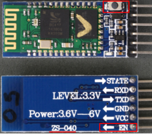
- HC-05 module with “KEY” pin:
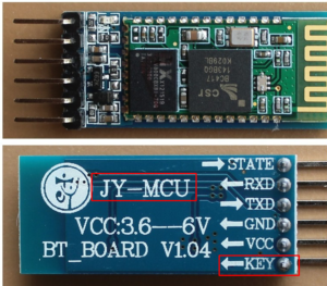
In both situations, you need to set baud rate to 115200, and (optionally) change the name and password. For “EN” module, please follow this tutorial, for “KEY” module, follow this. Basically, in both situations you need to switch the bluetooth module to AT mode, and change baud rate, name and password with these commands:
- AT+NAME=HC05-YOUR-NAME
- AT+PSWD=PASSWORD
- AT+UART=115200,1,0
3. Soldering LEDs
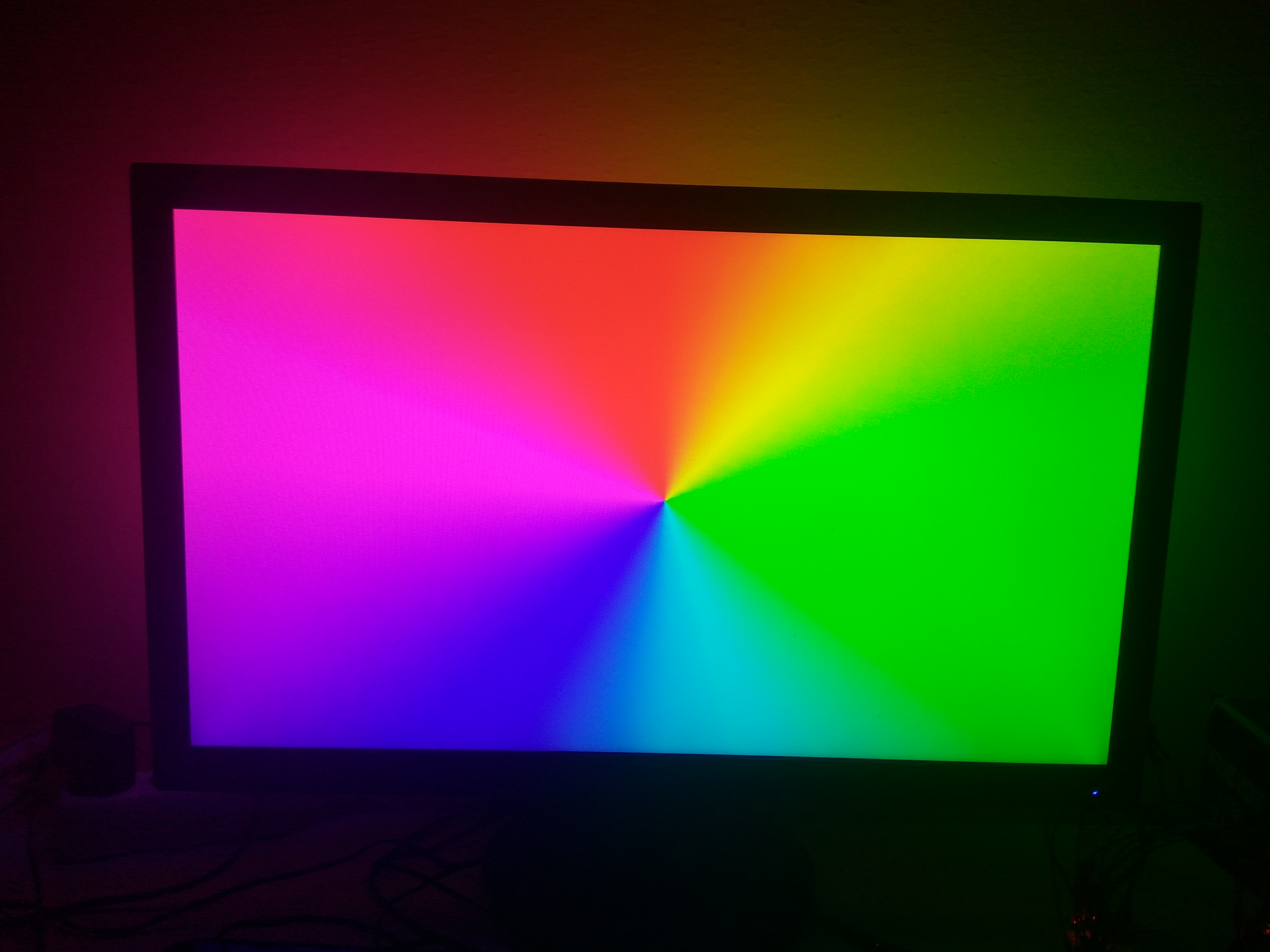
In this part, you will need some basic soldering tools and skills. The main idea is to mount your LEDs to the back of your monitor. I have used 1m long strip with 30 WS2812b LEDs. You can get them from aliexpress or ebay, just type “ws2812b” in search. The price is around 5-10$. When you will be buying your LEDs, do not forget to buy appropriate power source. The 1m LED stripe with 30 LEDs must have 5V voltage and approx 2A current. With 60 LEDs you will need roughly 5V and 4A power source.
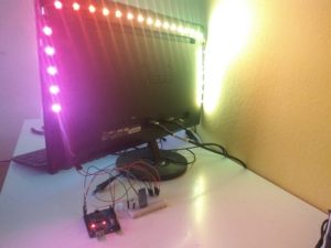
My LED stripe come with sticky label on its back, so I basically cut the stripe into 3 pieces, stick them to the sides of my monitor and soldered them together.
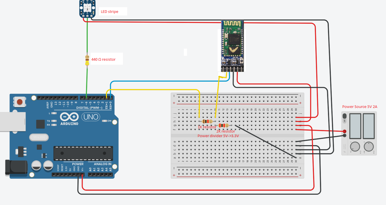
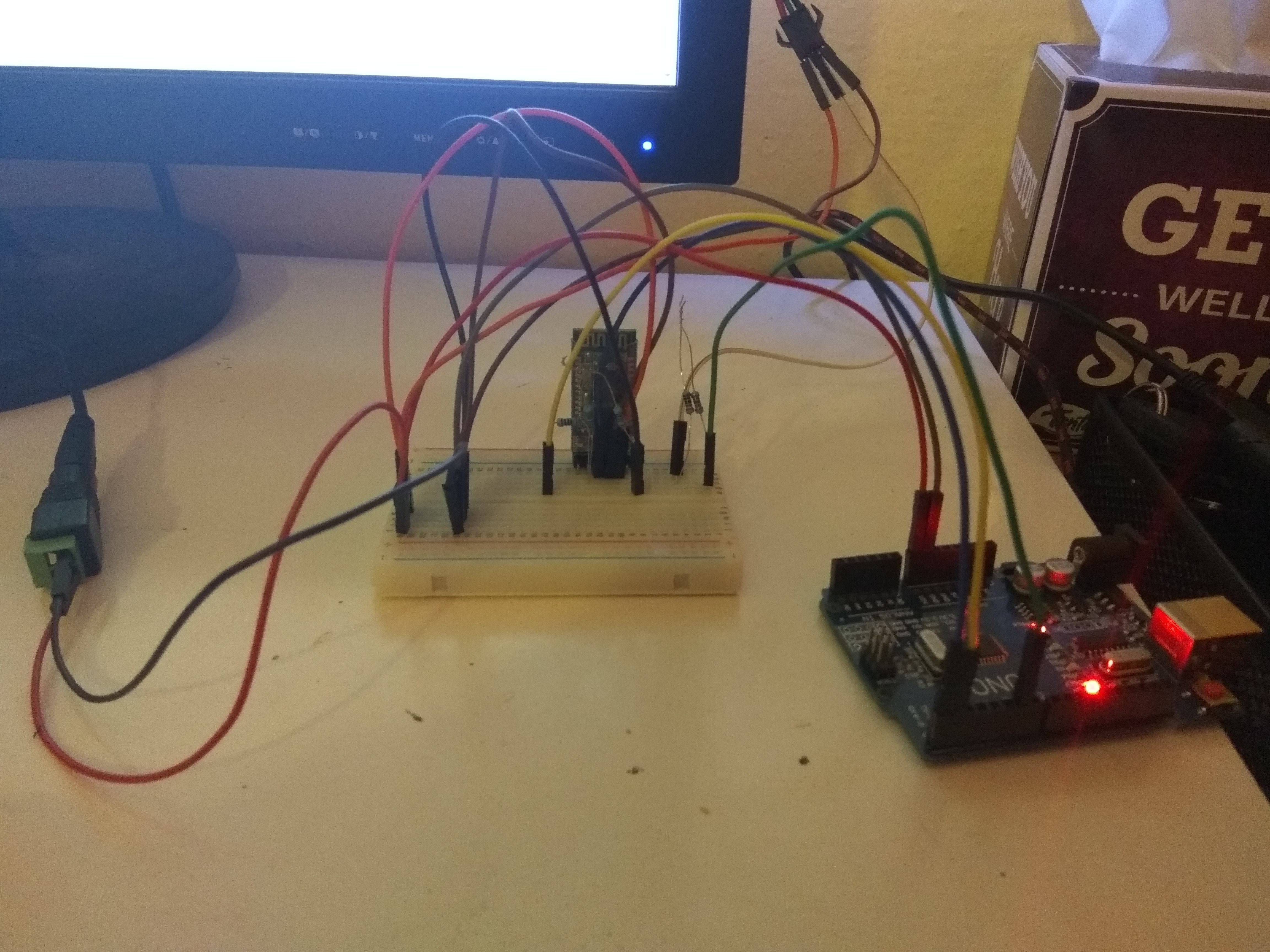
4. Building final circuit
In this step, you now have your bluetooth module configured and LEDs sticked to your monitor’s back. Now we will connect it with arduino into one circuit. There are some parts, that you must understand:
- Between Arduino’s pin, that we will use for data output and data input on LED stripe should be 440Ω resistor, to protect the first LED
- HC-05 RX pin should take 3.3V. But we have 5V power supply, so we need to add “voltage divider” using 1K and 2K Ω resistors. You can learn about voltage dividers more here
Final circuit looks like this:
5. Arduino code
In this step, you need to connect Arduino to the PC via usb. From Arduino IDE upload this code. You should set two properties:
- NUM_LEDS to number of your leds (in my case 30)
- DATA_PIN to pin number, that you are using for LEDs, (in my case 6)
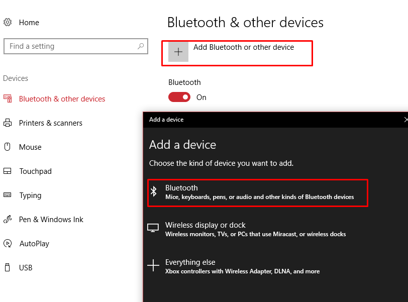
6. Pair HC-05 with windows
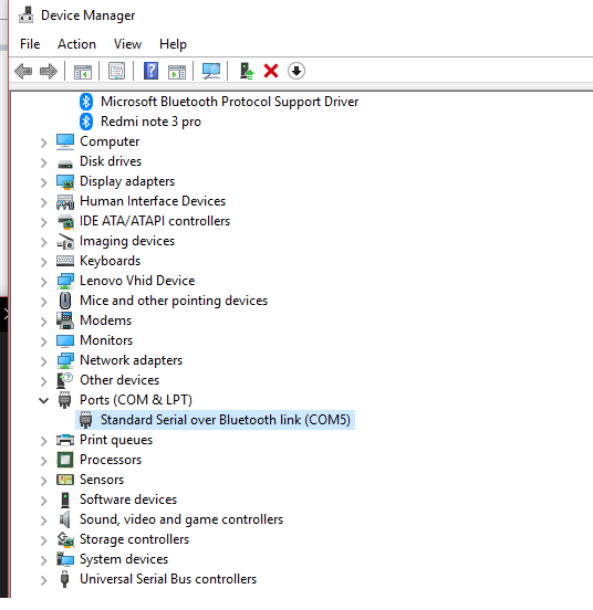
Now you need to pair HC-05 module with windows. The circuit must be enabled, so the bluetooth module will be active. After pairing, find COM port of this device in Device Manager.
7. Ambilight using Ambibox
You must install AmbiBox application. You can get it from here. It is tested to work on windows 8 and 10. After installation, you should set LED count and COM port (to number from Device Manager)
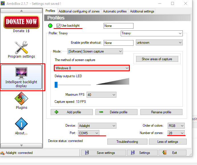
Ambibox supports configuration of zones, so you can configure particular zones for your case. Now you should have your arduino disconnected from pc and receiving data over bluetooth 🙂 .